by Ian Gray, Oilwatch Transformer Services
The primary purpose of transformer maintenance is to ensure the internal and external parts of the transformer and accessories are kept in good condition and “fit for purpose” and able to always operate safely. A secondary and equally essential purpose is to maintain a historical record of the condition of the transformer.
Maintenance, availability and reliability are closely related, and the transformer user has to specify a level of maintenance that will ensure an acceptable level of transformer reliability.
Transformer operation and maintenance cycle
A transformer is usually a robust apparatus with very good reliability requiring relatively low maintenance. During the life of a transformer, the user must establish a maintenance strategy that will ensure the appropriate level of reliability and an optimized operational life.
The operational life of a transformer begins with commissioning after it is installed in a substation. Once in operation, a maintenance strategy starts to be applied. An optimised maintenance strategy will provide the required availability and reliability of the transformer over its lifetime at minimum cost. It is the goal of good maintenance to detect any abnormalities before they cause unnecessary damage.
Once an abnormality is detected, then some or all of the available diagnostic techniques set out by various Standards organisation (IEC/IEEE) and CIGRE Technical brochures can be applied to evaluate the severity of the problem, localize it, and determine if the transformer can return to service with or without a restriction on operation.
If necessary, the appropriate corrective action can then be performed, or depending on the transformer condition, it may be appropriate to invoke a more intensive intervention on the transformer. Ultimately, it may be decided that it is time to refurbish or repair the transformer or even to replace it, depending on the results of an evaluation that will include consideration of the safety (both to site staff and the general public), the potential environmental consequences and the system reliability aspects of continued operation.
Maintenance strategy: Condition monitoring.
Any maintenance strategy, other than the simplest time-based strategy, will depend on feedback of the condition of the transformer. To be useful however, a condition monitoring task must be technically and economically justifiable. The technical justification depends on whether a condition can be detected and corrected before a loss of performance occurs.
Figure 1 shows a theoretical condition in terms of degradation as a function of time for a transformer. Tree important points can be observed:
- At point X, the condition is still good but is starting to change
- At point Y, the condition has changed enough to be detectable by a specific diagnostic technique
- At point Z, the condition has deteriorated sufficiently to cause a transformer failure
To be technically feasible, a condition monitoring task should have the ability to:
- Detect a given condition change that is relatively small compare to the condition change where the failure occurs
- Have a measurement or inspection interval that is smaller than ΔT[XY]+ΔT[YZ] to allow detection before failure occurs
- Have a period ΔT[YZ] that is long enough to be able to take the preventive action (transformer outage).

Transformer maintenance can be done periodically or as condition-based maintenance. The latter is usually the most economical way of doing maintenance. Recommended maintenances are then done based on one or more of the following: inspections, analysis of oil samples, electrical measurements, test of equipment, measurement of temperatures by using a heat sensitive camera, monitoring (off-line and/or on-line).
Maintenance in energised condition
For personal safety reasons, only a limited amount of maintenance activities should be performed on the transformer when it is in operation. When safety precautions have been taken the following maintenance can be done in energised condition:
- Inspection for leakages, cracks in porcelain bushings, check of auxiliary equipment, etc.
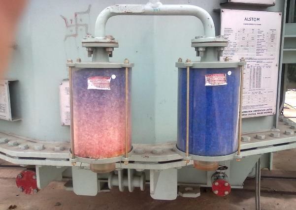
- Check drying material in the dehydrating breather (See Figure 2 - Transformer breather).
- Measurement of temperatures of joints, bushings, etc., by using a heat sensitive camera.
- Insulating oil samples
Maintenance in de-energised condition
The purpose of this technical document is to highlight some of the short falls in insulating fluid maintenance but some mention of external inspection and de-energised maintenance needs consideration by transformer owners as this aspect has an influence on fluid maintenance.
Before starting maintenance work, the transformer must be disconnected from the network and earthed. When the circuit breaker and the isolator have been opened, they shall be locked in open position to prevent inadvertently closing during maintenance work.
Items to be considered:
- Bushing gaskets: If leaks occur, tightening usually will help, if the gasket has lost its elasticity, it must be replaced. The reason for loss of elasticity could be excessive heating or ageing.
- Cover gaskets, valves, and gaskets of the tap changer. If there are leakages, bolt tightening will often help
- Welded joints: Leaking joints can be repaired only by welding or suitable sealants
- Cleaning contaminated bushings (by cleaning agent, e.g., methylated spirit)
- Cleaning glasses on gas relay, thermometer, and liquid level indicator
- Functional inspection and testing of applicable accessories
- Move tap changer through all positions a few times, all types of tap changers
- Liquid sampling from bottom drain valve for larger units as required
- Check drying material in the dehydrating breather
- Amend surface treatment defects
- Oil and insulation maintenance, drying and reclaiming
- Tap-changer maintenance
- Inspection and maintenance on the active part should not be performed unless there are unambiguous indications of defects.
Transformer liquid and insulation
The task of oil in a transformer is to act as an electrical insulation and to transfer heat from the transformer’s active parts into coolers. Oil acts as a good electrical insulation only as long as it is satisfactorily dry and clean and to understand the condition requires the data from the insulating fluid sample. Measured parameters or observed states are assessed against pre-defined criteria (limit values) for acceptable service condition. Maintenance is only performed when a change in equipment condition warrants taking action.
The oil tests can be classified into three types: Routine tests, complementary tests, and special tests.
- The routine tests aim to evaluate basic characteristics that identify the oil proprieties, such as colour, moisture, dielectric breakdown voltage, etc.
- Complementary tests supply more insight into the oil status, especially if there is any anomaly in the routine tests.
- Special tests give an overall view of the transformer oil in terms of physical and chemical properties. This classification is portrayed in Figure 3, and Figure 4 shows the ‘type of dielectric liquid’ problem.
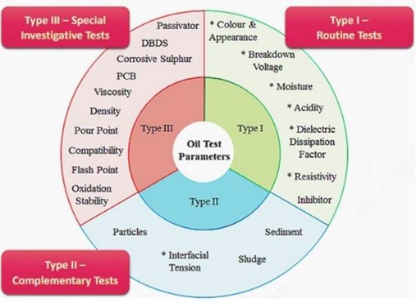

(Figures 3 and 4 Courtesy: EEP-Salem Alshahrani, CIGRE A2 Reference 761. To establish the limit values, refer to IEC60422 and IEEE Standard C57.106)
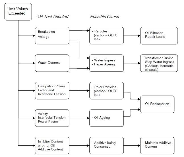
Decision process in cases of oil tests returning "abnormal values”
It is recommended that the transformer owner refers to the various CIGRE Technical Brochures and IEC/IEEE Standards or appropriate technical information. The transformer manufacturer may also be contacted to obtain information about transformer design and possible the problems or safety considerations. To provide some guidance the extract from CIGRE Technical Brochure 445 Guide for Transformer Maintenance is given below:
Moisture management
This is only discussed briefly here, since this subject is complex as are the mitigation processes.
Moisture balance between the oil and the solid insulation implies that most of the moisture will gather in the paper insulation. Moisture in insulation is one of the dominant ageing accelerators. It is recommended to dry the insulation when the moisture exceeds a certain level. Drying of the insulation and oil is recommended for large distribution and power transformers since this can be technically and economically motivated. Equipment for drying transformers at site is available and the residual moisture in the insulation will be less than 1% after drying with low frequency heating equipment. During drying the transformer must be de-energised. Drying time can vary from one to two weeks depending on the transformer size, amount of insulation and initial moisture level in the insulation.
Transformer reliability survey
There is limited local knowledge as to failure rate of transformers but the two case studies that follow suggest that the failure causes due to improper maintenance and repairs (6,02% and 3,22 % respectively) might be higher than figures given in the CIGRE Study (Collection of 964 major failures which occurred in the period 1996 to 2010).
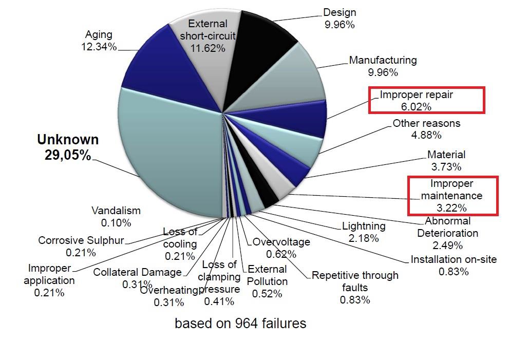
Any situation which requires the equipment to be removed from service for a period longer than seven days for investigation, remedial work or replacement is a major failure. Where repairs are required, these involve major remedial work, often requiring the transformer to be removed from its plinth and returned to the factory. A major failure would require at least the opening of the tank, including the tap changer tank or an exchange of bushings. Also, a reliable indication that the condition of the transformer prevents a safe operation should be counted as a major failure if remedial work (longer than seven days) is needed for restoring original service capability (e.g. detection of strong PDs).
Case study 1
Example of a unit affected by improper repair
The case of a 1000 kVA, 11 kV plant distribution transformer, which failed two hours after being re-energised following repairs to the off-load tap changer where the maintenance contractor had recommended this outage based on their interpretation of the oil insulation data (dissolved gas and fluid insulation quality).
The ensuing investigation to establish the root cause revealed the following:
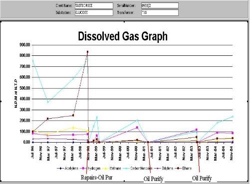
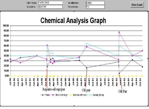
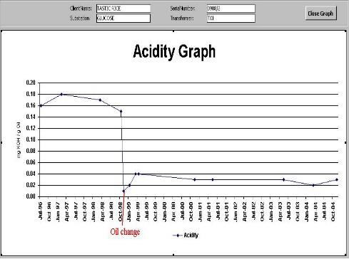
The dissolved gas analysis did not indicate any failure mode and the insulation fluid tests complied with IEC 60422. The historic data showed that the unit had previously undergone an oil replacement/purification process to mitigate an out of specification acidity condition (See Figures 7,8,9).
Observations made during the inspection (tear-down investigation)
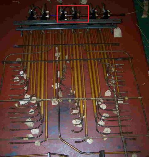
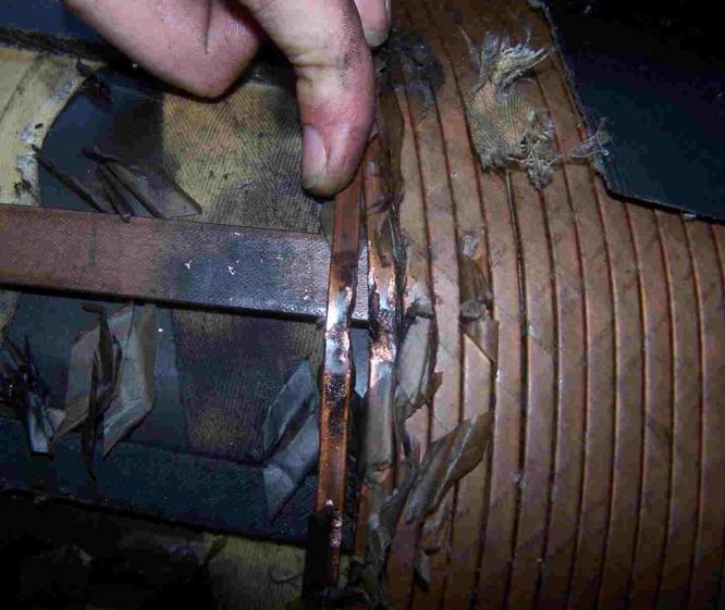
The outlet from the conservator tank is positioned above the off-load tap changer in the area where the flash on the tap changer occurred. (See Exhibit 1). This primary fault on the tap changer caused a secondary fault on the center phase winding (telescoping)-short circuit.
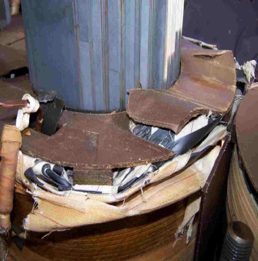
During the duration of this fault the voltage disturbance on the two winding in series would have produced very large electromagnetic forces, approximately 202 (or 400 times) the normal stress related to the current and thus the windings would have tried to shift with respect to each coil, resulting in damage at the coil ends.
Note: The vertical or axial force causes the low voltage and high voltage windings to shift with respect to each other, a condition called “telescoping” (See Exhibit 2).
Mechanism of failure
The primary fault of flash over on the center phase of the off-load tap changer mechanism was a direct result of contaminated insulating oil when the fluid handling process was reviewed.
The insulating oil was drained into 210 litre drums and the transformer’s main cover was removed for inspection of the upper connections. The tap changer’s HV bushing/tail connections were tightened. Note: The maintenance contractor claimed they were found to be marginally loose but according to the owner’s electrician there was no evidence of this.
The transformer was re-assembled and the oil was pumped back. This process will result in contamination of the insulating oil by water and particulate matter. This combination of water and particulate matter can lower the dielectric strength (kV) of the insulating oil up to 90%.
The transformer was re-energised without oil treatment and fluid insulation quality testing, which is highly irresponsible and is a non-conformance with IEC 60422 - Section 12.1 ‘Replacement of oil transformers rated below 72.5 kV and in switchgear and associated equipment’.
Insulating liquids used in transformers, circuit breakers, and high-voltage bushings require proper testing and maintenance to keep them in good condition. Liquid insulation that is not in good condition may cause damage to equipment and become a hazard to personnel.
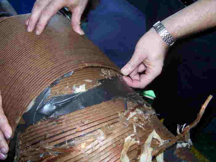
The flashover (contaminated insulation fluid) caused a secondary fault in the 7th to 9th layer of the centre winding as result of a short circuit (mechanical forces) and not direct thermal damage of the insulation as claimed by the maintenance contractor. (See Exhibits 3 & 4 showing the damage).
Conclusion
The transformer prior to maintenance was showing normal operation. There was no evidence of any internal fault occurring based on the transformer oil analysis. The recommendation by the maintenance contractor for an internal inspection was not based on any accepted diagnostic codes. The maintenance procedures implemented resulted in the transformer failure.
Case study 2
Example of a unit affected by improper maintenance
The case of a 800 kVA, 11 kV, plant distribution transformer at a petrol refinery which failed two days after being re-energised following a reconditioning process (degassing, drying and filtration) to mitigate the deterioration of the fluid (oil) insulation quality.
Note: Reconditioning (purification), also sometimes referred to as “drying & filtration,” “vacuum degassing & filtration” or “physical treatment,” is a process that eliminates or reduces some contaminants (moisture, gas, suspended material, etc.).
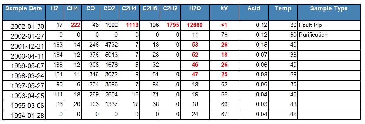
The record of the dissolved gas analysis (DGA) and insulation fluid quality (water: dielectric strength: acidity: oil) Temperature results are shown in Table 1 and the Duval Pentagon plot of DGA data is given in Figure 10.
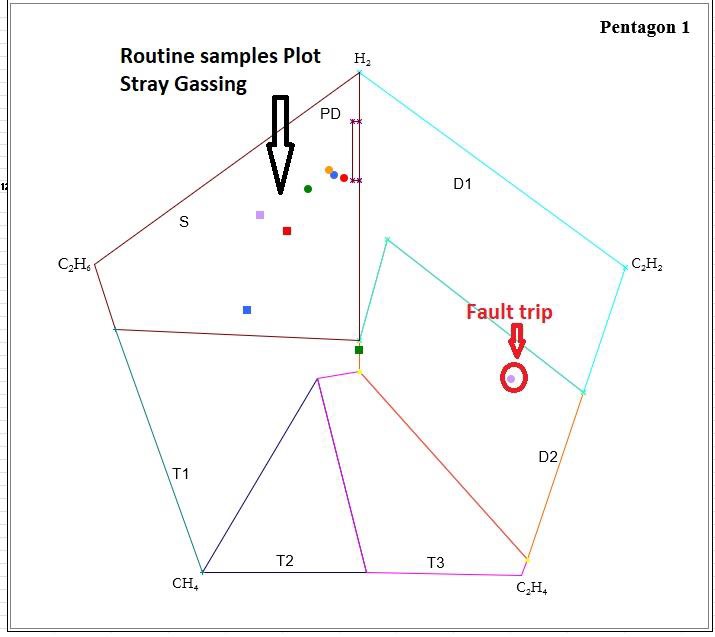
Fault Type D2-Discharges of high energy
IEC 60599 Examples:
- Flashover, tracking, or arcing of high local energy or with power follow-through.
- Short circuits between low voltage and ground, connectors, windings, bushings and tank, copper bus and tank, windings, and core, in oil duct, turret.
- Closed loops between two adjacent conductors around the main magnetic flux, insulated bolts of core, metal rings holding core legs.
Failure Investigation
The oil reconditioning was completed (with the power off) and the oil quality laboratory test returned results that the transformer fluid insulation was suitable for energised operation (Table 1).
Note: Compliance to IEC 60422-TABLE 3-Reccommended limits for mineral insulating oils after filling in new electrical equipment prior to energisation.
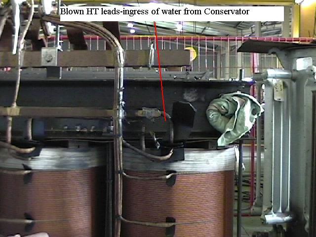
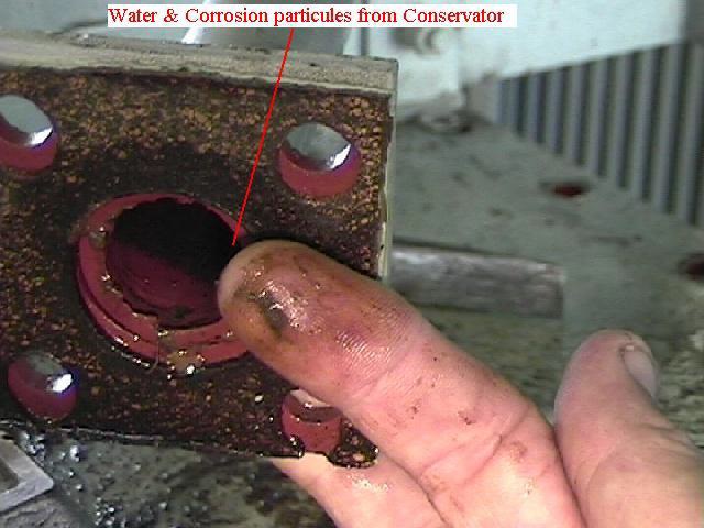
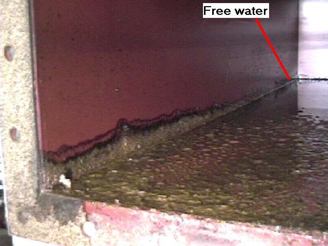
The detanking and inspection revealed that the primary fault was arcing from HT leads to the side of the main tank (distance of arc was about 300 mm – see Figure 11), caused by the ingress of contaminated oil from the conservator tank - see Figure 12.
Note: The unit failed at the peak loading cycle.
Root cause
The conservator tank was not inspected as per the scope of work (see Figure 13)
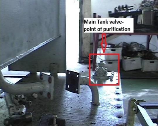
Oil purification via the Conservator tank was bypassed in favour of the value on the top of the main tank (see Figure 14). The purification value on the main tank would have resulted in limited agitation in the conservator tank, i.e., with the purification plant process at 2500 litres per hour there would be sufficient pressure back feeding into the conservator tank to agitate the free water and particulate matter.
This positive pressure would have arrested any ingress of free water during the purification process.
Note: This would explain the after-purification oil sample conforming to the standard.
The water/particulate (contamination) ingress was attracted to the HV leads, the oil at this point having very low insulation value <0,5 kV, arcing occurred to the grounded channel iron.
Points of consideration (root cause) and improvement
The transformer had a history of rapid water saturation of the silica gel breather coupled with signification water in oil increase. Breather saturation was occurring from the top, i.e., moisture coming via the transformer as opposed to the atmosphere.
The transformer oil analysis results must be checked coupled with external condition, i.e., state of breather and leaks. The source of water should be established prior to any reconditioning process.
Note: CIGRÉ Technical Brochures and IEC Standards provides detail on related topics of oil treatment
The oil purification of transformers can be an effective means to remove water and contamination, but certain safety procedures must be followed, one of them being checking the conservator tank prior to any oil processing. The oil is circulated through the reconditioning equipment, typically being taken from the bottom of the tank of the electrical equipment and returned to the top. The return delivery should be made smoothly and horizontally at or near the top oil level to avoid, as far as possible, mixing cleaned oil with oil that has not yet passed through the reconditioning unit.
Transformers maintenance management in Southern Africa
Transformer asset managers try to achieve the required levels of safety and reliability from their fleet of transformers at minimum cost. Knowing the transformer’s condition is therefore essential for efficient transformer asset management decisions.
There is over reliance by transformer owners to outsource maintenance activities (routine works) to external contractors when this can be provided by their own staff. Different levels of outsourcing may be used to execute the maintenance activities.
Some the of transformer maintenance specialised tasks (OLTC inspections, special diagnostic works) may be assigned to specialist external contractors.
Economic aspects also must be taken in consideration when deciding about the extent of outsourcing. Common tasks may be outsourced only in the case where it would not be efficient to keep their own staff and is usually less costly than external contractors. Other factors such as remote locations, and the level of specialization needed may influence which resources are used.
There is a lack of local knowledge about the proper maintenance standards and the work of authorities like IEC and CIGRE and their various Groups & Mirror Committees.
References
- CIGRE Technical Brochure 445: Guide for Transformer Maintenance
- CIGRE: Condition assessment of power transformers, A2 Reference 761: Working Group A2.49 March 2019
- IEC Publication 60422, Edition 4.0 2013-01: Mineral insulating oils in electrical equipment – Supervision and maintenance guidance
- IEC Publication 60599: “Mineral Oil-Impregnated Equipment in Service – Guide to the Interpretation of Dissolved and Free Gases Analysis”,
- Guide to transformer maintenance (1st, 2nd, and 3rd editions)
About the author
Ian Gray is a member of the South African Chemical Institute and the South Africa mirror committee for IEC TC 10 (International Electro technical Commission)/CIGRE (SA-Regional Advisory Group). He also serves on the SANAS/SABS 290 committee (Mineral insulating oils - Management of polychlorinated biphenyls (PCBs). His over 35 years of experience includes transformer oil testing, diagnostics and internal inspections coupled with the ISO17025 Quality management system.
Contact Oilwatch, Phone 087 238-2188, support@oilwatch.co.za, www.oilwatch.co.za


