Information from Megger
The application of narrowband dielectric frequency response (NB DFR) on HV CVTs to reduce the risk of failure of HV instrument transformers in the transmission system.
A case study: A utility’s SCADA system indicated a loss of voltage in one phase. Since 765 kV CVTs provide the voltage information to all control, metering, and protection systems at this location, failure of the CVT (CVT-1) corresponding to that specific phase was immediately suspected. Tests, which were conducted on the capacitance and power factor (PF) at line frequency, confirmed insulation failure of C1 sections B2 and B3 of CVT-1 (see Figures 1 and 2).

Figure 1: Megger delta control results of CVT-1’s C1 sections B1 to B4 (Note elevated PF results, significant discrepancies in capacitance between sections, and high, non-zero VDFs, which indicate PF voltage dependencies, in sections B2 and B3).

Figure 2: CVT simplified scheme.
For additional insights, 250 V narrowband dielectric frequency response (NB DFR) tests, comprising PF measurements between 1 and 500 Hz, were performed on all four sections of CVT-1 (Figure 3).

Figure 3: NB DFR plot of failed CVT 1’s C1 sections B1 to B4 (Note the PF at 60 Hz in the 250 V NB DFR test results above. When compared to the 10 kV PF test results in Figure 1 significant, abnormal voltage dependencies become obvious.).
The customer reported this fairly obvious failure as an over-pressure event and replaced CVT-1 with CVT-1R. CVT-1R was similarly tested. Its acceptable capacitance and PF and NB DFR test results serve as helpful, normative references for CVT test results (Figures 4 and 5).

Figure 4: Acceptable capacitance and PF test results for replacement CVT-1R (Note that a ratio test performed at 10 kV and a digital multimeter indicated acceptable ratio results).
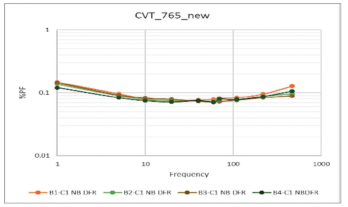
Figure 5: Acceptable NB DFR test results for replacement CVT-1R C1 sections B1 to B4.
While replacing CVT-1, the testing specialist noticed a stain on the surface of the adjacent phase CVT (CVT-2, Figure 6).
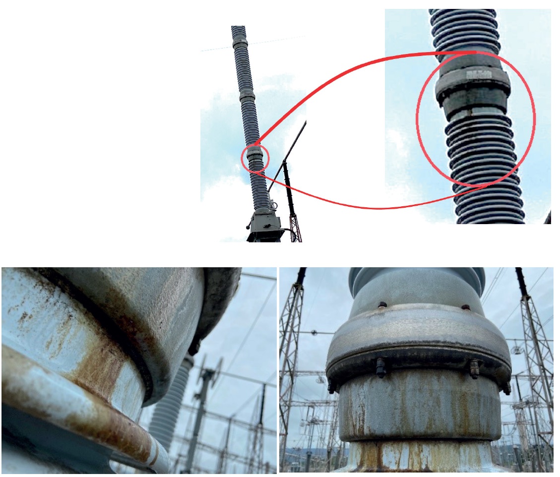
Figure 6: CVT-2 as found during visual inspection (Note that a ratio test performed at 10 kV and a digital multimeter indicated acceptable ratio results.).
CVT-2 was reporting an expected voltage in SCADA but given the failure of CVT-1 and convenient access to the testing equipment, capacitance and PF tests and NB DFR tests were performed on CVT-2 too (Figures 7 to 10). These tests revealed insulation failure in CVT-2.

Figure 7: C1-B1 section capacitance and PF test results for stained CVT-2.
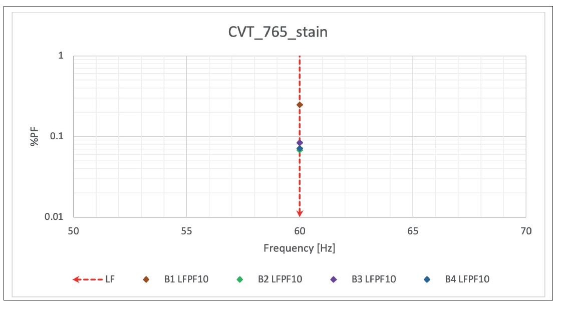
Figure 8: 10 kV line frequency PF test results for C1 sections Bi to B4 of CVT-2 (Note the elevated PF for Ci-B1 section (0,25%) relative to the other three sections (~0,08%)).
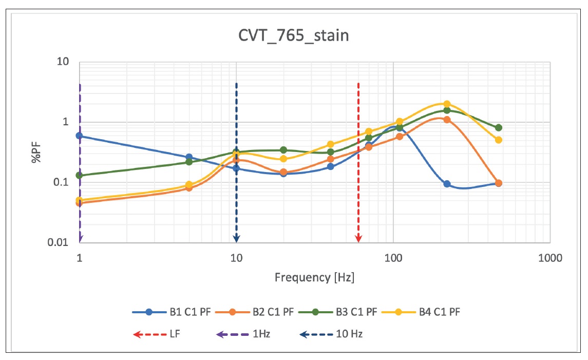
Figure 9: NB DFR test results 1 to 500 Hz on CVT-2 (Note that all units connected in series have been affected and the dielectric response presents an atypical response for all four sections. The 1 Hz test result of C1 section B1 revealed a different behaviour compared to the other sections and a PF tip-up test (Figure 10), was performed to verify its voltage dependence.).
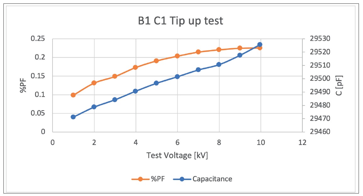
Figure 10: Power factor tip-up test results for C1-B1 section of CVT-2.
A disassembly of CVT-2 confirmed significant damage to its C1 – B1 section (Figure 11).
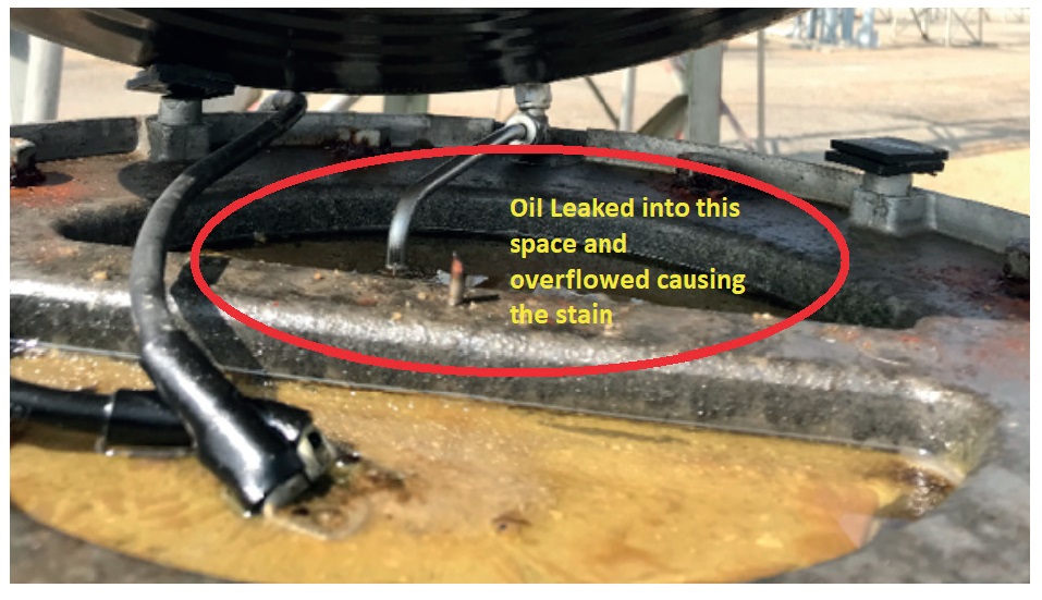
Figure 11: Oil overflow due to puncture on top of C1-B1 section.
A puncture was found in the C1-B1 section, and oil was missing from the top portion of C1-B1 section. Although its insulation integrity was compromised, its ratio was not affected. CVT-2 was also replaced.
Lessons learned
- A CVT in good condition should have a very low PF value (at 20°C) <0,2% at 1 Hz (Figure 5).
- The utility performs monthly visual inspections but did not notice the oil leak between C1 sections of CVT-2. Testing averted its likely failure.
- NB DFR testing will be incorporated in the utility’s future routine maintenance of CVTs.
- The Megger Delta 4000 and TDX120 provide both basic (capacitance and PF) and advanced (NB DFR) diagnostic insulation testing. Atypical NB DFR results should be further investigated with a full dielectric frequency response (DFR) test using the Megger IDAX300.
Contact Marie-Claude Rasendra, Megger, marie-claude.rasendra@megger.com
